github.com/SpacehuhnTech/WiFiDuck @1.1.0
Chat with this repoBrowse by type
What it actually does AI analysis from the code graph — generated when you open this
README
WiFi Duck

- About
- Usage
- Support us
- Buy Hardware
- Malduino W
- DSTIKE WiFi Duck
- DIY Hardware
- Atmega32u4 Development Boards
- ESP8266 Development Boards
- Connections
- PCB
- Flash Software
- Flash Atmega32u4
- Flash ESP8266
- Unbrick Atmega32u4
- Scripting
- Basics
- Functions
- Standard Keys
- Modifier Keys
- Other Keys
- Examples
- CLI Commands
- General
- SPIFFS File Management
- How to Debug
- Development
- Edit Web Files
- Translate Keyboard Layout
- Disclaimer
- License
- Credits
About
This open-source project aims to provide a user-friendly tool to learn about keystroke injection attacks and 'BadUSBs'.
By emulating a USB keyboard, tools like this can gain full access to any computer with a USB port in a matter of seconds!
This is made possible by the fact that keyboards are trusted by computers. You can have full control over a computer with just a keyboard.
A BadUSB pretends to be a keyboard to the computer to send keystrokes.
But unlike a human, it can type hundreds of characters per second.
By using a simple scripting language, it's easy to make BadUSBs type whatever you want.
With the WiFi Duck, you can simply connect via WiFi to manage all scripts from within a web interface. This means that, unlike other BadUSBs, you don't need to install an app, log in, compile or copy scripts to an SD card.
Usage
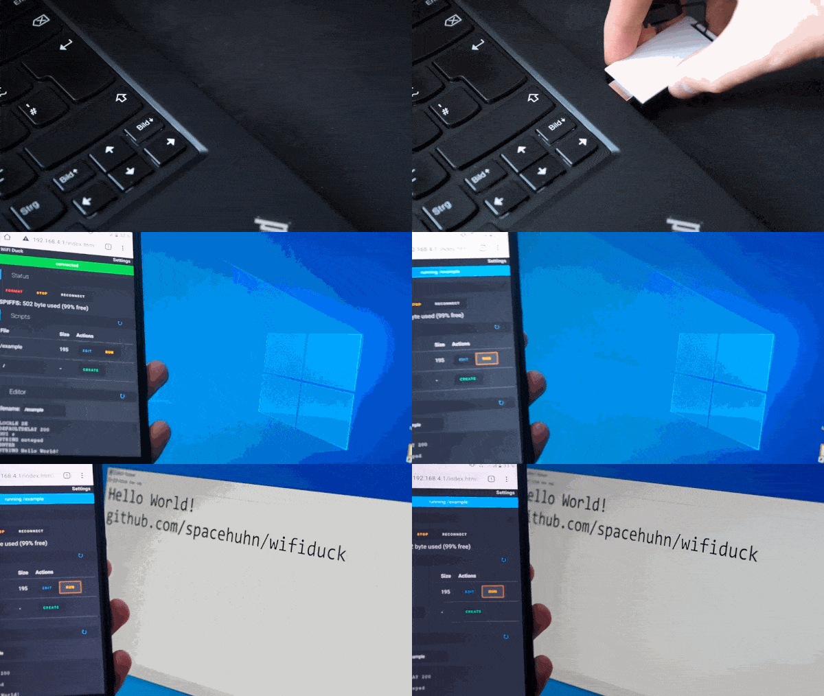
<b>Watch the full video</b>
- Plug in your WiFi Duck
- Connect to the WiFi network
wifiduckwith the passwordwifiduck - Open a browser and visit
192.168.4.1 - Write, save and run your first Ducky Script
- [Recommended] Open
Settings(top right corner) and update SSID and password
Help I forgot the password:
Flash the ESP8266, but make sure that you select Erase Flash: Sketch + WiFi Settings
under Tools in the Arduino IDE.
If you have further questions, check out the issue section.
Support us
Hey, do you like this kind of project?
It took a huge amount of effort to create!
To make sure we can keep working on free and open-source projects like this,
please consider becoming a :heart: Sponsor or support us via :coffee: Ko-fi.
Visit spacehuhn.com to learn more about us. :chicken:

Buy Hardware
Malduino W

<b>Go to Maltronics.com</b>
A nicely encased, inconspicuous looking BadUSB by Maltronics.
Having USB-A and USB-C makes it compatible with all kind of devices.
It comes flashed with the WiFi Duck firmware and works plug and play.
ℹ️ Documentation can be found here
DSTIKE WiFi Duck

<b>Got to DSTIKE.com</b>
A custom designed development board which comes preflashed with this software by Travis Lin.
You can update the ESP8266 over the air and flash the Atmega32u4 via Arduino, all while enclosed in its neat little case.
📺 Watch the How to Update Tutorial here.
If you wish to develop your own software or help improve this one, the 8-bit DIP-switch makes it easy for you to access the Atmega32u4 or ESP8266 independently. For more info see Flash Software.
| Mode | Atmega32u4 | ESP8266 | DIP-switch | Image |
|---|---|---|---|---|
| Default Operating Mode | USB | On | 10101101 |  |
| Atmega32u4 Flash Mode | USB | Off | 10101010 |  |
| ESP8266 Flash Mode | Off | USB | 01011101 |  |
DIY Hardware
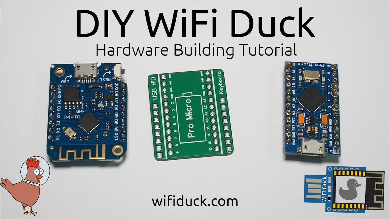
<b>Watch the video tutorial</b>
To build a WiFi Duck yourself, you need the following hardware:
An Atmega32u4 development board (see the list below)
An ESP8266 or ESP8285 development board (see the list below)
* Optional: A single Neopixel (WS2812b) or Dotstar (APA102) LED
To flash the microcontrollers you need a computer and USB cable.
If you're a beginner, it's recommended you wire everything together on a breadboard first!
In this case, you'd also need a breadboard with a couple of jumper wires.
If you wish to solder everything together into a small gadget, you also need soldering equipment.
You can use any Atmega32u4 or ESP8266 based development board,
but if you have no idea where to start, here's a list.
:warning: Keep in mind that you will need both microcontrollers!
The Atmega32u4 to act as USB keyboard, and the ESP8266 for WiFi.
Atmega32u4 Development Boards
- Arduino Leonardo
- Arduino Micro
- Sparkfun Pro Micro
- CJMCU Beetle
- SS Micro
:bangbang: DIGISPARK or other ATTINY85 based development boards, are NOT supported! :bangbang:
ESP8266 Development Boards
- NodeMCU 1.0 (ESP-12E Module)
- LOLIN(WEMOS) D1 Mini
- LOLIN(WEMOS) D1 Mini Pro
- LOLIN(WEMOS) D1 Mini Lite
Connections
A map of pins that need to be connected.
| ESP8266 | Atmega32u4 |
|---|---|
D1 alias GPIO 5 |
3 alias SCL |
D2 alias GPIO 4 |
2 alias SDA |
GND |
GND |
Ideally, you want the Atmega32u4 to power the ESP8266, so it can run on one USB connection, instead of having to always plug in both.
To share power between both chips, you need a voltage regulator that takes 5V and turns it into 3.3V.
That's because USB runs on 5V, but the ESP8266 only takes 3.3V. Luckily most development boards have such a regulator on board.
DO NOT CONNECT ESP8266 VCC to the ATMEGA32u4 VCC, it will kill the ESP826. Instead look for the 5V or VIN pin on your dev board, as those will be connected to the regulator.
| ESP8266 Dev Board | Atmega32u4 |
|---|---|
5V or VIN |
RAW, 5V or VIN |
To add a Neopixel (WS2812b) LED:
| Atmega32u4 | Neopixel LED |
|---|---|
7* |
DI alias Data, In |
5V alias VCC |
5V alias VCC |
GND |
GND |
* The Data pin can be changed later on in the software, pin 7 is just an example.

PCB
To make the DIY process easier, I designed a little PCB.
You solder a Pro Micro board on one side and a Wemos d1 mini or NodeMCU board (depending on the PCB) on the other side.
That's it. You don't even have to solder all pins,
just the ones mentioned in Connections, excluding the LED.


Design Files:
* Pro Micro + Wemos d1 mini: https://easyeda.com/Spacehuhn/wifi-duck
* Pro Micro + NodeMCU: https://easyeda.com/Spacehuhn/diy-wifi-duck-pro-micro-nodemcu
You can also order them on OSHPark: * Pro Micro + Wemos d1 mini: https://oshpark.com/shared_projects/ARCED9je * Pro Micro + NodeMCU: https://oshpark.com/shared_projects/XUuUH1HB
Flash Software
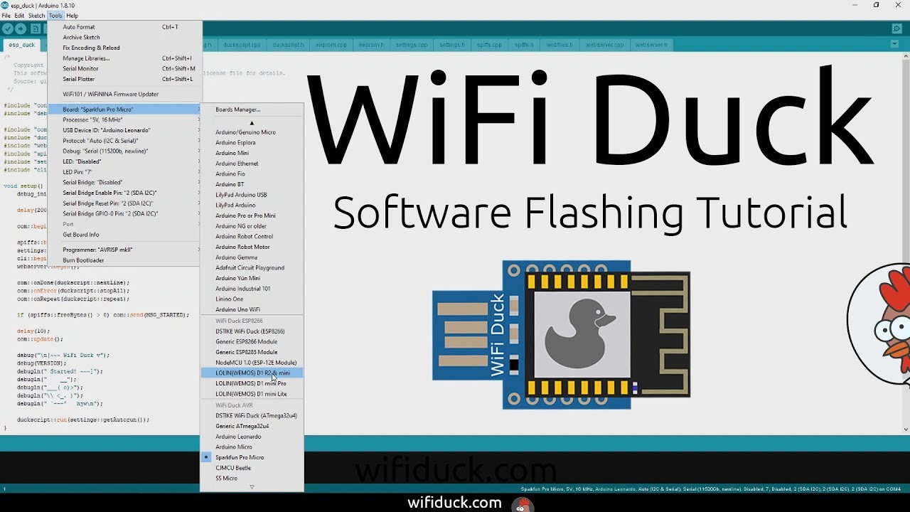
<b>Watch the video tutorial</b>
- Download and install the Arduino IDE.
- Start the Arduino IDE, go to
File>Preferences. - At Additional Board Manager ULRs enter
https://raw.githubusercontent.com/spacehuhn/hardware/master/wifiduck/package_wifiduck_index.json. You can add multiple URLs, separating them with commas. - Go to
Tools>Board>Board Manager, search forwifi duckand installWiFi Duck AVR BoardsandWiFi Duck ESP8266 Boards. - Download and extract this repository or git clone it.
If you can't find the COM port of ESP8266 board, then you're probably missing the right drivers. Here are links to drivers of the 2 most used UART chips on ESP8266 development boards: - :floppy_disk: CP2102 - :floppy_disk: CH340
Flash Atmega32u4
- Open
atmegaduck/atmega_duck.inowith the Arduino IDE. - Under
Tools>Boardin theWiFi Duck AVRsection, select your board; for example,Sparkfun Pro Micro. - Connect the Atmega32u4 board via USB and select its port under
Tools>Port. - Optional: Under
Toolsyou can enable the LED and set its pin. You can also change the USB ID to make it appear as a certain type of keyboard. - Press Upload.
Flash ESP8266
- Open
esp_duck/esp_duck.inowith the Arduino IDE. - Under
Tools>Boardin theWiFi Duck ESP8266section, select your board. For exampleNodeMCU 1.0 (ESP-12E Module). - Connect the ESP8266 board via USB and select its port under
Tools>Port. - Press Upload.
Pro Tip: If the ESP8266 is already running this software
and you just want to update it, you don't have to connect it via USB.
You can update it over the air! Simply connect to the wifiduck network (default password is wifiduck).
Then in Arduino at Tools > Port you should now see a network port.
Select it and press Upload.
Note: After the initial flashing, the ESP8266 has to format its memory, so it might take a minute until it's fully ready.
If you connected the RGB LED: * Blue LED = Connection working * Green LED = Device ready
Unbrick Atmega32u4
If you flashed your Atmega32u4 board with the wrong bootloader,
it will no longer appear in the port selection after you connect it.
To solve this, you need to:
- Connect the reset pin
RSTto groundGND. Preferably with a jumper wires, because you need to be able to disconnect it quickly. - Open a sketch,
atmegaduck/atmega_duck.inoor an empty sketch.
Make sure to have the correct board selected underTools>Board! - Connect the board with the wire still connected.
- Press
Uploadand as soon as you seeCompiling...turn toUploading..., disconnect the wire.
Now it should flash the sketch and the correct bootloader.
Scripting
Basics
Keys are separated by a single space.
Everything written in a single line gets pressed and released at the same time.
To write text, use the STRING function.
It's compatible to Ducky Script, which was developed by the wonderful people at Hak5.
| Example | Explanation |
|---|---|
| WINDOWS |
r | Type the Windows key and then the r key | | WINDOWS r | Press the Windows key and the r key simultaneously | | STRING WINDOWS r | Write WINDOWS r |
Functions
| Command | Example | Description |
|---|---|---|
REM |
REM Hello World! |
Comment |
DEFAULTDELAY or DEFAULT_DELAY |
DEFAULTDELAY 200 |
Time in ms between every command |
DELAY |
DELAY 1000 |
Delay in ms |
STRING |
STRING Hello World! |
Types the following string |
REPEAT or REPLAY |
REPEAT 3 |
Repeats the last command n times |
LOCALE |
LOCALE DE |
Sets the keyboard layout. Available: DE, ES, GB, US, DK, RU, FR |
KEYCODE |
KEYCODE 0x02 0x04 |
Types a specific key code (modifier, key1[, ..., key6]) in decimal or hexadecimal |
LED |
LED 40 20 10 |
Changes the color of the LED in decimal RGB values (0-255) |
Standard Keys
| Key |
|---|
a - z |
A - Z |
0 - 9 |
F1 - F12 |
Modifier Keys
| Key |
|---|
CTRL or CONTROL |
SHIFT |
ALT |
WINDOWS or GUI |
Other Keys
| Key |
|---|
ENTER |
MENU or APP |
DELETE |
HOME |
INSERT |
PAGEUP |
PAGEDOWN |
UP or UPARROW |
DOWN or DOWNARROW |
LEFT or LEFTARROW |
RIGHT or RIGHTARROW |
TAB |
END |
ESC or ESCAPE |
SPACE |
PAUSE or BREAK |
CAPSLOCK |
NUMLOCK |
PRINTSCREEN |
SCROLLLOCK |
Examples
``` REM Hello World fo
Core symbols most depended-on inside this repo
Shape
Languages
Modules by API surface
For agents
$ claude mcp add WiFiDuck \
  -- python -m otcore.mcp_server <graph>