github.com/BlueAndi/Pixelix @v9.1.0
Chat with this repoBrowse by type
What it actually does AI analysis from the code graph — generated when you open this
README
PIXELIX

Full RGB LED matrix, based on an ESP32 and WS2812B LEDs.





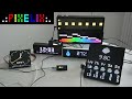

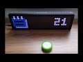
Click on the preview to see the video.
Table of Content
- Motivation
- Introduction
- Features
- Original Setup
- Attention
- Supported Development Boards
- Recommendation
- Special Variants
- Installation
- Very First Startup
- Variant 1: Configure WiFi station SSID and passphrase using a browser
- Variant 2: Configure WiFi station SSID and passphrase using a serial terminal
- PIXELIX Is Ready
- User Interface
- One button control
- Two button control (LILYGO® T-Display ESP32-S3)
- Three button control (Ulanzi TC001)
- Remote button
- Details
- FAQ
- Where to change panel topology of the LED matrix?
- How to change text properties?
- The display only shows a error code, like "E4". What does that mean?
- How can I use animated icons?
- How do I know that my sensor is recognized?
- Why do I see sometimes values from the LDR in the SensorPlugin, although no LDR is installed?
- How can I use alternative icons?
- Is it possible to use a font with 8px height?
- How to configure the date/time format?
- How to configure my own list of plugins?
- Is there an easy way to rotate the display by 180° ? I need to turn the display when putting it into a housing
- Used Libraries
- Issues, Ideas And Bugs
- License
- Contribution
Motivation
My initial goal was to have a remote display that would show multiple kind of information and run reliably 24/7. Can be connected to the local network via WiFi and controlled via REST API or Websocket. PIXELIX was born!
Introduction
The PIXELIX firmware is for ESP32 boards that controls a RGB LED matrix or a TFT display. It can be used to display time, date, weather, text, animations and etc. It doesn't require any cloud connection, even its not required to have a smarthome system. But with its REST and MQTT API it fits perfect with Home Assistant or any other smarthome system.
Features
- Supports 32x8 LED matrix size out of the box. Its possible to cascade another matrix to have a longer display.
- Supports some small TFT displays to simulate a LED matrix in retro style.
- Display static or scrolling text, as well as static (BMP and GIF) or animated icons (GIF).
- Includes a web interface for configuration and control.
- Supports REST and MQTT API for remote control and integration with other systems, like Home Assistant.
- Extendable with custom effects and animations by plugins. See list of plugins.
- Its plugin concept allows to scale for different development boards.
Please note, that not every feature might be available for all kind of development boards. E.g. for MQTT support you need a development board with 8 MB flash or more, except for the Ulanzi TC001. See the config<variant>.ini configuration files in ./config folder.
| Some impressions | |
|---|---|
 |
 |
 |
 |
 |
... |
Original Setup
The original setup for development and the first release was:
- ESP32 DevKitV1
- WS2812B 5050 8x32 RGB Flexible LED Matrix Panel
- Power supply 5 V / 4 A
The following shows the absolute minimal wiring setup e.g. for the ESP32 DevKitV1. It may differ depended on your development board.

Attention
:warning: If you power the development board and the LED matrix via USB: Be very careful, because it may destroy your ESP32 board if the LED current is too high. Avoid increasing the LED display brightness or filling it complete with white pixels. Please use a external power supply with at least 5V / 4A.
:information_source: To avoid any damage on your hardware and by the way to your eyes ;-), PIXELIX starts up with a low brightness setting. Additional the max. current is limited by software.
Supported Development Boards
In the meantime several other boards are supported as well. You can find them in the list of boards. If your board is not listed in the main branch, please have a look in the Development branch too.
With the Ulanzi TC001 smart pixel clock you even don't need to assemble the electronic and mechanic together.
Recommendation
If you assemble your own Pixelix hardware, its recommended to use a development board with the following properties:
- 8 MB flash or more. 4 MB flash modules are still supported, but the functionality is limited.
- A esp32 dual core variant, which provides more processing power.
- PSRAM for images as internal RAM isn't that much available depended on the configured features.
Special Variants
Additional supported variants, which were original not in focus:
- LILYGO® TTGO T-Display ESP32 WiFi and Bluetooth Module Development Board For Arduino 1.14 Inch LCD
- LILYGO® T-Display ESP32-S3 1.9 inch ST7789 LCD Display Touch Screen Development Board
- Limited HUB75 panel support, configured for the ESP32-DoIt DevKit v1 and the Adafruit MatrixPortal S3 development board.
Although PIXELIX was designed to show information, that is pushed or pulled via REST API, the following sensors can be directly connected and evaluated:
- Temperature and humidity sensors DHTx
- Temperature and humidity sensors SHT3x
- Digitial microphone INMP441 for some sound reactive stuff.
Installation
The following steps are necessary for the first time and to get PIXELIX initial running on the target. Once it runs, later on the firmware and filesystem can be updated via the PIXELIX Updater: https://github.com/BlueAndi/PixelixUpdater. You can accesss the Updater through the submenu "Update" of PIXELIX's webinterface.
- Setup the toolchain.
- Build the software and check whether the toolchain works.
- Upload/Update the software and firmware to the target.
- Verify that the LED panel topology is correct and you see the "Hello World" on the display.
Note, that the LED panel topology and the display width/height can not be changed in the web interface. If its necessary, adapt first in ./config/display.ini the CONFIG_LED_MATRIX_WIDTH and CONFIG_LED_MATRIX_HEIGHT according your LED matrix and change CONFIG_LED_TOPO according to your physical panel topology. Take a look how your pixels are wired on the pcb and use the following page to choose the right one: https://github.com/Makuna/NeoPixelBus/wiki/Layout-objects
Very First Startup
When the device starts for the very first time, the WiFi station SSID and passphrase settings are empty. They can be configured in two possible ways:
- Using the browser and set them in the captive portal.
- Using a serial terminal connecting via USB.
Variant 1: Configure WiFi station SSID and passphrase using a browser
Restart the device and keep the button pressed until it shows the SSID of the WiFi access point, spawned by PIXELIX. Search for it with your mobile device and connect.
- SSID: pixelix-<DEVICE-ID>
- Passphrase: Luke, I am your father.
Depended on the type of device you are using for connecting to PIXELIX, you may get a notification that further information is necessary and automatically routed to the captive portal. In any other case enter the URL http://192.169.4.1 in the browser address field.
Use the following default credentials to get access to the PIXELIX web interface:
- User: luke
- Password: skywalker
Variant 2: Configure WiFi station SSID and passphrase using a serial terminal
Connect PIXELIX to your PC via USB and start a serial terminal. Use the following commands to set the WiFi SSID and passphrase of your home WiFi network:
- Write WiFi passphrase:
write wifi passphrase <your-passphrase> - Write WiFi SSID:
write wifi ssid <your-ssid> - Restart PIXELIX:
restart - Get IP-address:
get ip - Get hostname:
get hostname - Get status:
get status - A status of 0 means everything is ok.
- Other than 0, see their meaning in the low low level error code table. Note, the status of 1 is equal to E1 in the error code table and etc.
Use help to get a list of all supported commands.
PIXELIX Is Ready
After configuration, restart again and voila, PIXELIX will be available in your wifi network.
For changing whats displayed, go to its web interface. Use the same credentials than for the captive portal in variant 1. In the "Display" page you can change it according to your needs.
User Interface
Pixelix can be controlled with buttons. Most of the development boards are supported with just one user button.
One button control
- 1 short pulse: Activates the next slot.
- 2 short pulses: Activates the previous slot.
- 3 short pulses: Activates next fade effect.
- 4 short pulses: IP address is shown.
- 5 short pulses: Toggle display power on/off.
- Long pressed: Increases the display brightness until maximum and then decreases until minimum. After that it will again increases it and so on.
Two button control (LILYGO® T-Display ESP32-S3)
- Left button:
- 1 short pulses: Activates the previous slot.
- 2 short pulses: Toggle display power on/off.
- Long pressed: Decreases the display brightness until minimum.
- Right button
- 1 short pulse: Activates the next slot.
- 2 short pulses: Activates next fade effect.
- 3 short pulses: IP address is shown.
- Long pressed: Increases the display brightness until maximum.
Three button control (Ulanzi TC001)
- Left button:
- 1 short pulses: Activates the previous slot.
- Long pressed: Decreases the display brightness until minimum.
- Ok button:
- 1 short pulses: Activates next fade effect.
- 2 short pulses: IP address is shown.
- Long pressed: Toggle display power on/off.
- Right button
- 1 short pulse: Activates the next slot.
- Long pressed: Increases the display brightness until maximum.
Remote button
If the display's location is hard to reach, the remote user button feature can be used. It is controllable via REST API and perfect for remote buttons like the Shelly Button 1.
Details
- Home Assistant
- REST API
- MQTT API
- More information is in the documentation folder.
FAQ
Where to change panel topology of the LED matrix?
Adapt in `./config/display.ini
Core symbols most depended-on inside this repo
Shape
Languages
Modules by API surface
For agents
$ claude mcp add Pixelix \
  -- python -m otcore.mcp_server <graph>